Step 1: IC Extraction
In the last section, you installed the 40-pin Propeller chip and the 8-pin EEPROM into their sockets to test the board. Before we can continue, we need to remove the chips so that we don't overheat them or damage them when we continue soldering.
Tools Needed
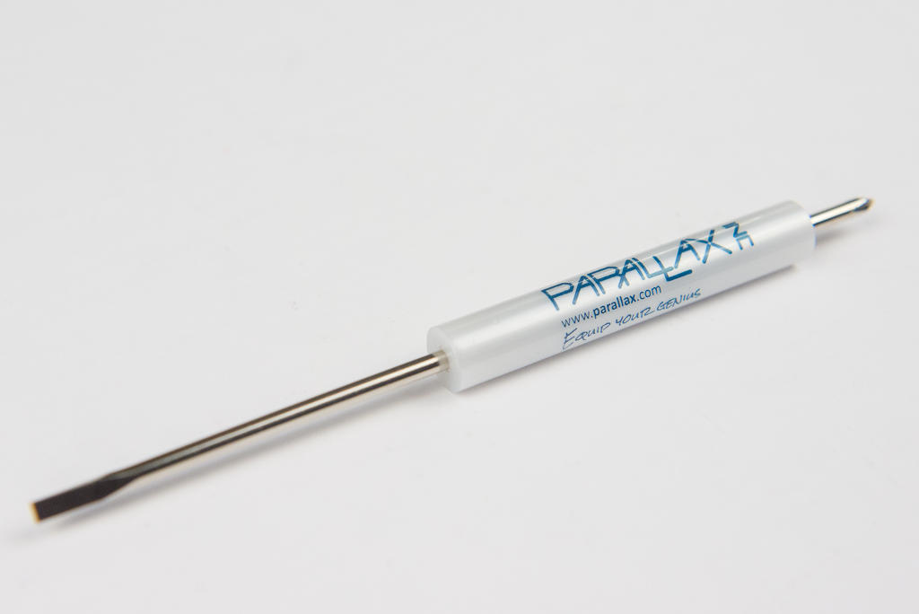
- Small flat-head screwdriver
Instructions
This section needs more photos!
-
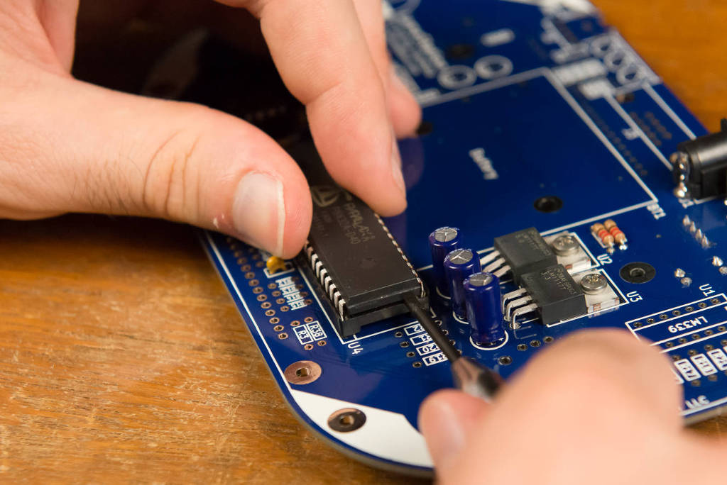
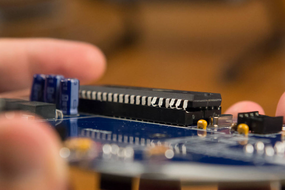
Starting at either end of the chip, insert the screw driver between the chip and the socket along the edge. Gently twist the screwdriver while gradually wedging it in between the chip and the socket.
-
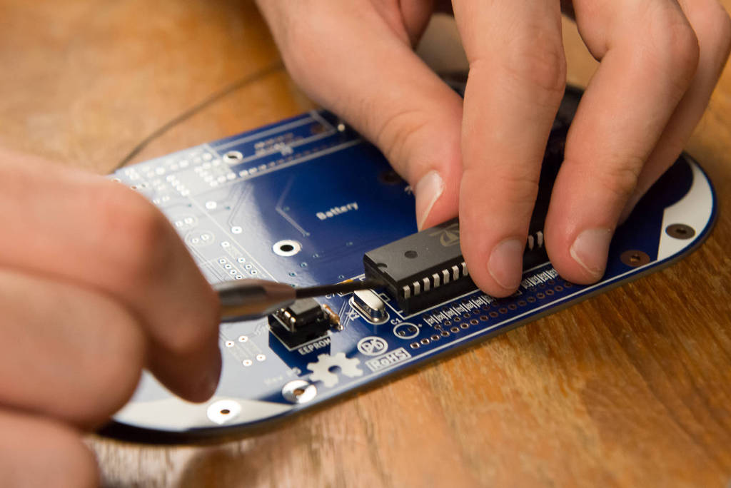
Once the chip comes a little loose, remove the screw driver and start the same process on the other end of the chip, gradually forcing more space in between them until the chip gently lifts free.
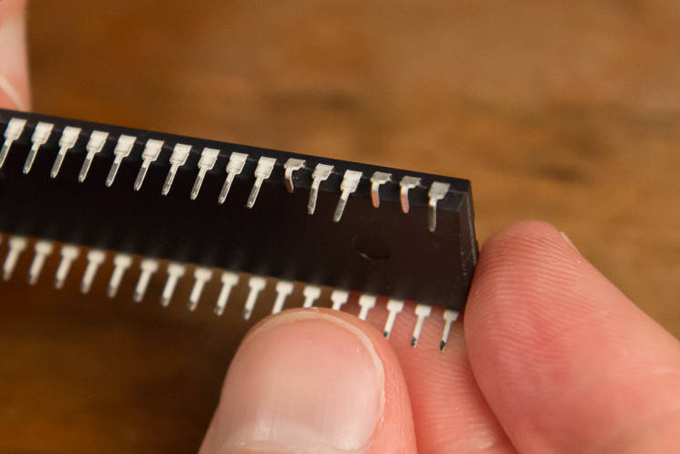
It can be a little tricky, so be patient, and make sure you do not bend the pins. No matter what you do, do not bend pins! Once they snap, that's it.
Do not bend the pins!
I can't emphasize this enough. While you need to bend it very slightly to fit it into the socket, bend an IC pin too far, and it will snap right off. Then it's game over for you until you replace the chip. Patience is a virtue; be VERY careful!
- NEED SECTION ON EEPROM REMOVAL
Protect you ICs!
Remember to place the ICs back on the special black foam they came on.
This foam protects the chip from ESD (electro-static-discharge). Electrostatic discharge are those tiny shocks you feel when you get close to a metallic door knob, or the same energy that makes your hair stand up when you rub your feet against the carpet at home. While it may seem harmless to people, it can be very bad news for our chip - so keep it safe!
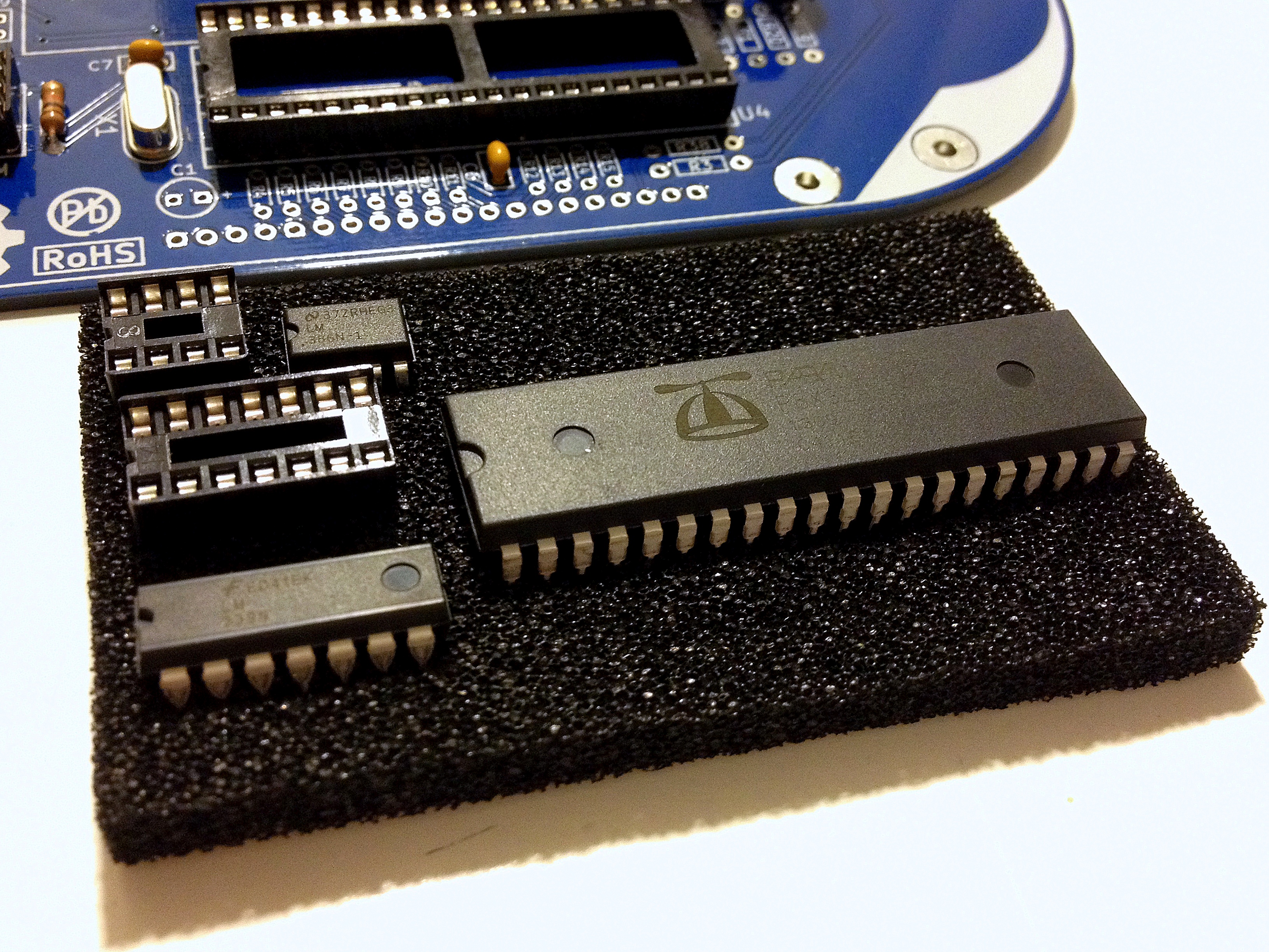
(NEED TO UPDATE PHOTO WITH LATEST PACKAGING)