Step 6: Light-Emitting Diode
This LED will turn on when the board is powered up.
SCHEMATIC OF POWER LED
Tools Needed
- Soldering iron
- Cutters
Parts Needed
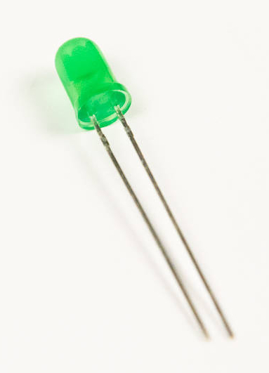
- 1 x light-emitting diode (LED)
Instructions
-
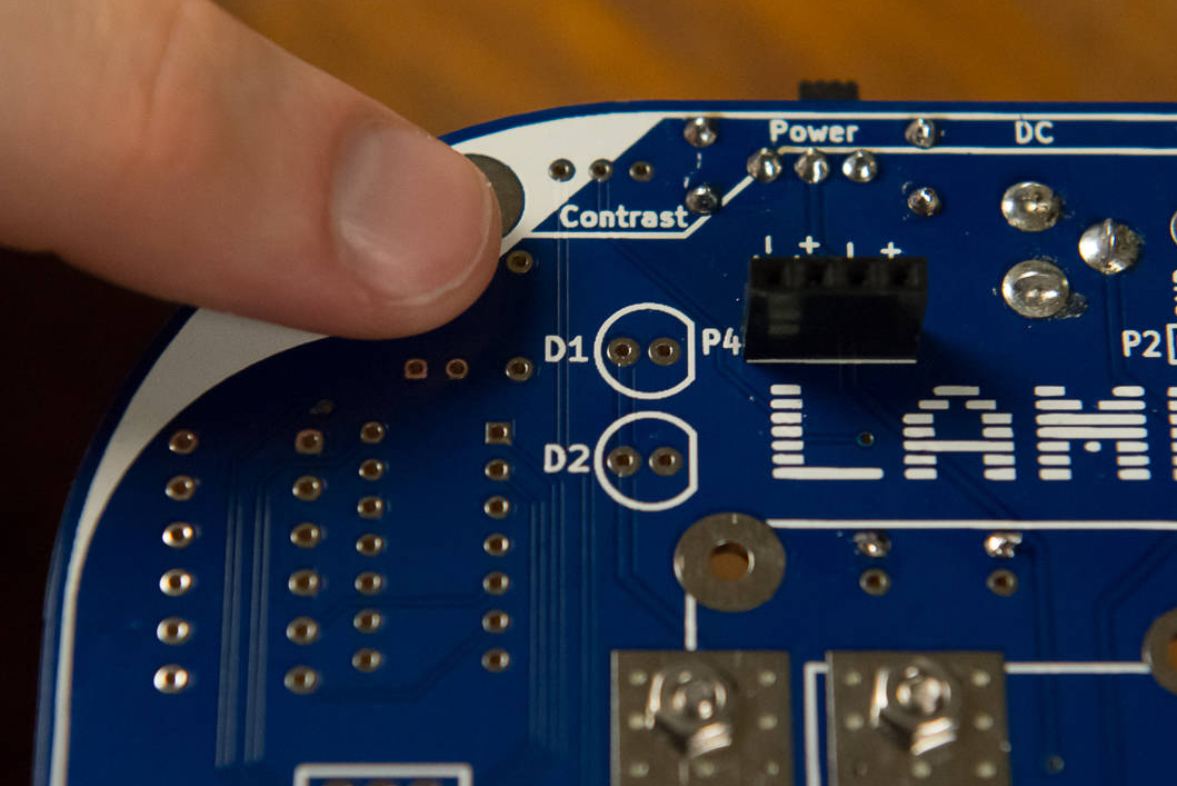
You will now be installing an LED to D1. Find the footprint for D1 on the board. You will notice that it has a flat edge on one side of the footprint.
-
Insert the LED into the board. Carefully notice that the LED has the same flat edge. You will also notice that one of the leads, or wires coming out of the LED, is shorter than the other, and the shorter one is one the same side as the flat edge. These both indicate the negative terminal of the LED.


-
Bend the lead wires back and solder away.
