Step 3: Capacitors
We will now be installing three 100μF capacitors into C3, C4, and C5.
WHAT IS AN ELECTROLYTIC CAPACITOR?
Tools Needed
- Soldering iron
- Cutter
Parts Needed
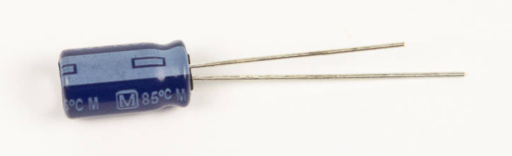
- 3 x 100μF capacitors
Instructions
-
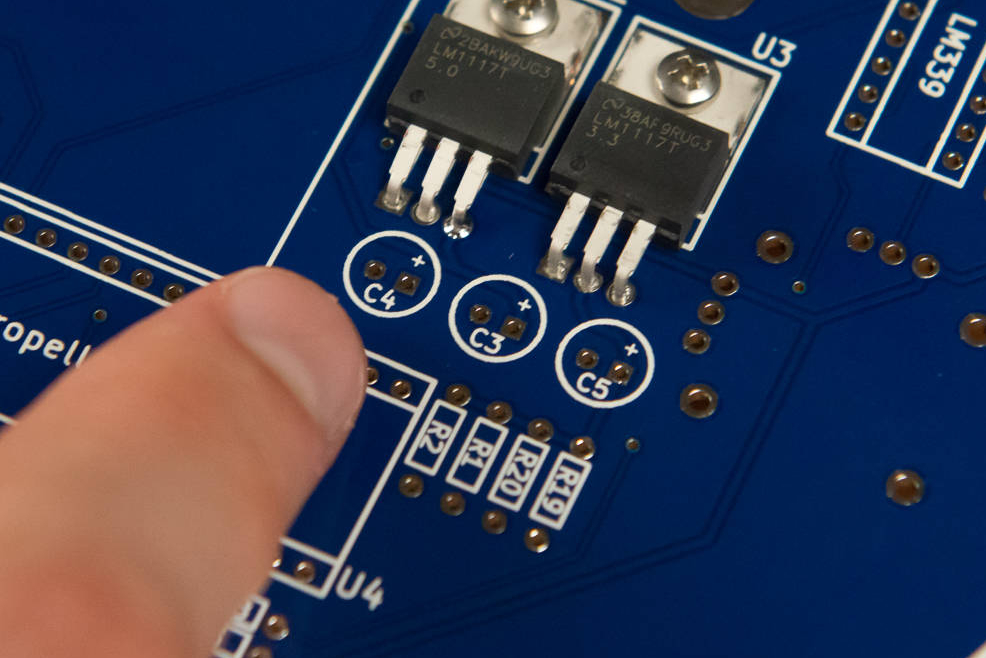
Find the footprints on the board. These are right next to the regulators that we just installed.
-
These capacitors are polarized, which means they have to be inserted in a certain direction to work right.
Do not insert the capacitor backwards
This type of capacitor may burst when the LameStation is powered if installed incorrectly.
You can determine the positive and negative terminals by looking at the body of the capacitor. On the side of one of the pins, you will find a strip of minus signs printed on the side. This is the negative terminal.
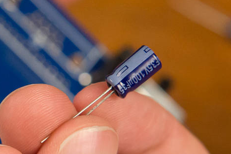
You can also tell by the length of the capacitor leads, or the wires that come out of it. The longer lead is the positive terminal.

Now looking at the PCB, the capacitor's footprint will have two holes, and on one side, there will be a plus sign.
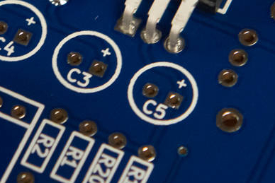
This indicates the positive terminal, so make sure that the strip of minus signs faces the other side, away from the plus sign.
-
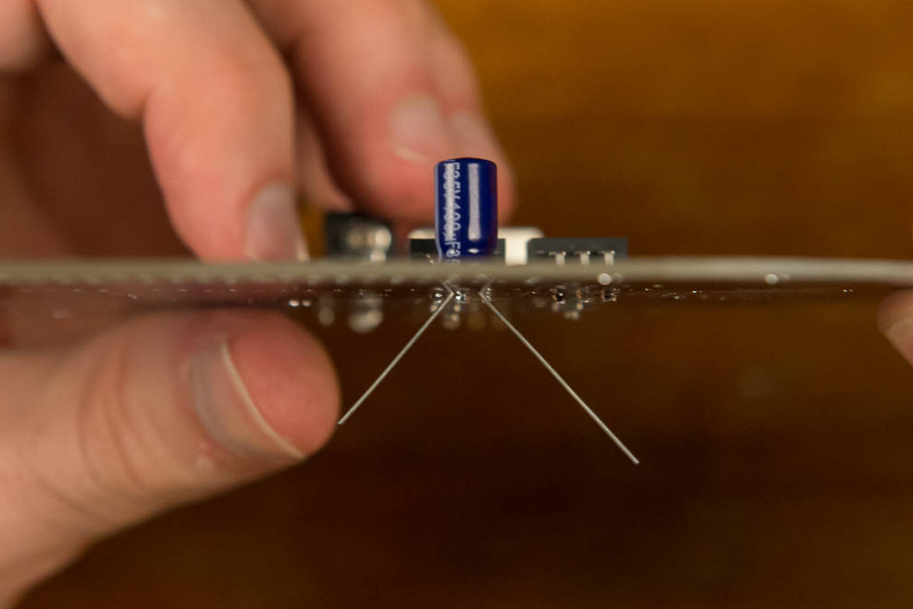
To get the capacitors to stay on the board while soldering, bend the leads away from each other so that they will hold onto the board. You will clip these off later, so you don't need to worry about these touching.
Seat the capacitors flush with the board
There must be enough clearance to seat the cover plate at the end.

-
Solder the capacitors into place. These big capacitors have a lot of metal in them, so they may be a little hard to solder. Just be patient and don't be afraid to hold the iron to the board. Just DO NOT touch the capacitors after soldering them, as they will be hot.

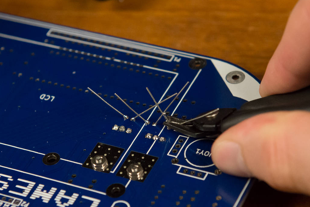
-
Clip the capacitor leads. Make sure you get them close enough so that none of the leads will touch on accident.