Step 3: Soldering
In this section, we show you how this manual works by having you solder your first component onto the board.
Reading This Manual
Each Step page follows roughly the same outline.
- First, a list of tools needed to the complete the section.
- Second, the parts to be attached.
- Third, the instructions for part using said tools.
It's all quite nice.
Step Example
Step Blah: Adding the Blah
Today we're going to blah blah blah...
Tools Needed
- Blah blah ...
Parts Needed
- 1 x blah ...
Instructions
- First you blah ...
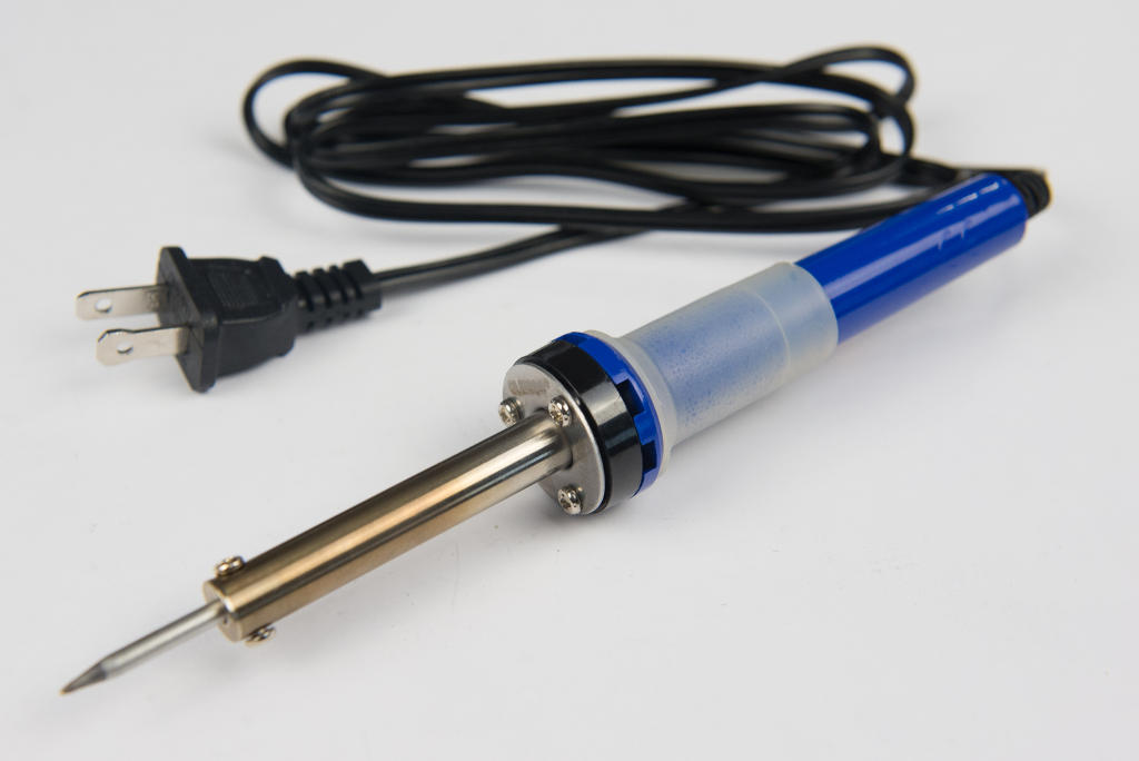
Tools Needed
So what is a soldering iron anyway? It's a boring way to say a super hot, several hundred degree pen that can put a hole in your table in an instant! YEAH!
Operating by the same principles as your toaster, it's literally like plugging in all the power from your wall outlet and concentrating it into one tiny point.
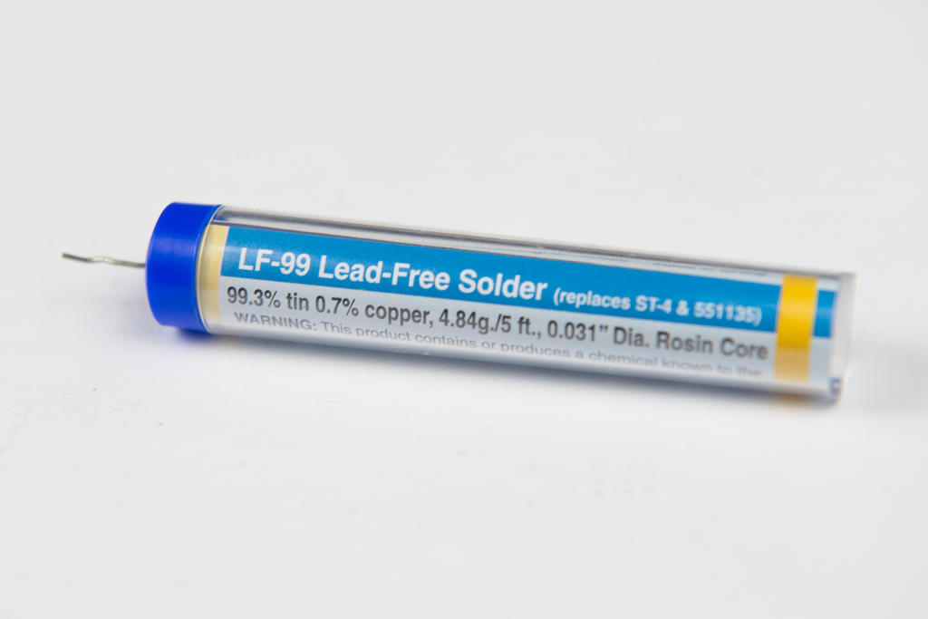
But why do something so awesome? Well, here's where it gets even cooler. A soldering iron is used to fuse two metal things together! It does this by melting a small amount of metal (in this kit, primarily tin), in between the two surfaces. This metal that we melt is called solder.
INSERT DIAGRAM OF SOLDER FILLING METAL JOINTS
Soldering Iron
Solder
You'll discover pretty quickly that it can be next to impossible to get components to stay on the board while soldering. You can try lots of different things. You can:
- Try to sandwich your board between two large objects somehow.
- Try to press your board on the table just right.
- Try to use those weird helping hands things, or a vice or something.
- Some other thing.
INSERT PICTURES OF UNSUCCESSFUL SOLDERING POSITIONING ATTEMPTS
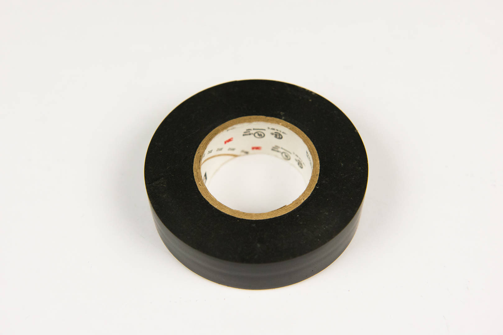
This is a matter of personal preference, but I find all of those things to be more trouble than they're worth, when you can literally just tape the component to the board and have it stay there without any complaints.
So that's what I do now. I just tape it to the board, and everyone's happy. Everyone being me, of course.
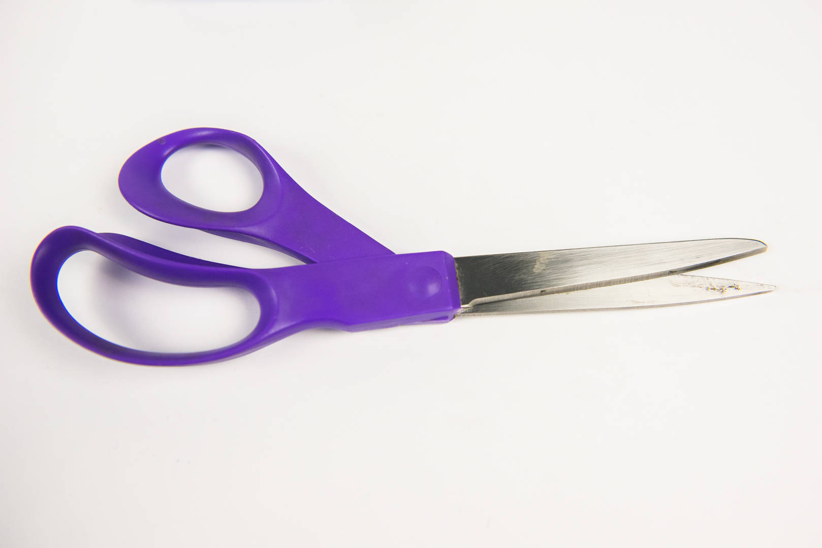
Oh, and you'll probably need scissors to cut the tape. Just saying...
Electrical Tape
Scissors
Parts Needed
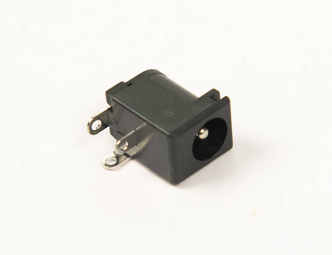
- 1 x DC barrel jack
- 1 x Board
Instructions
-
Unroll the plastic component bag labeled "1 & 2: Power", and find the DC barrel jack, as pictured above. All parts are organized in bags in the order in which they are used during assembly.
-
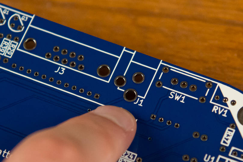
A footprint is a white outline that helps specify where certain parts are intended to fit and how. Find the footprint for this component. Each footprint has a tiny label on the board next to it. This barrel jack goes into J1, so look for it. Most components are on the back, with a few special ones in front.
-
You always want to solder the component onto the side with the footprint, otherwise it will be wrong, may not work, or worse.
-
Cut yourself some electrical tape to hold components in place. You'll be able to use this over and over again, so cut a good amount. Not too short that it won't stick, but not too long that it gets in the way.
Only use electrical tape
Other tapes may leave sticky residue or melt while soldering.

-
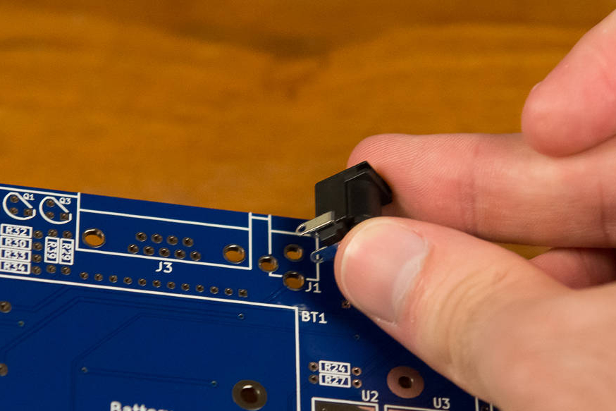
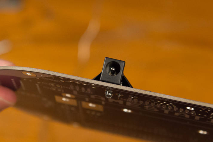
Tape the barrel jack to the board. Make sure it sticks on both sides so that the barrel jack stays flat, or flush with, the board when you flip it over. If it isn't flat against the board, and you begin to solder it, it's going to be next to impossible to fix, so there will always be a gap. So make sure it's flat before you start to solder.
-
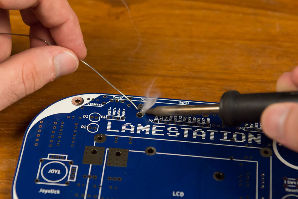
Flip the board over. Now you're going to solder the DC barrel jack into J1. Soldering is tricky. It's tempting to use the iron to melt the solder directly, but that doesn't work very well, as it burns off the flux in the solder, leaving none left to clean the surface of the board to improve solder wetting. Make sure to hold the iron flat so that the tip is flat against the metal on the board. So don't do that! Instead, use the iron to heat the metal pad on the board, then start melting the solder onto the board. This will ensure that the solder is able to bond with both surfaces. INSERT PICTURE OF HOLDING IRON FLAT AGAINST BOARD
-
 Solder doesn't always have to have a shiny finish. In fact, some
solders, like lead-free, it's very difficult to do so. It may end up
having more of a frosted-looking finish than metallic, and that's
okay, as long as it has a good shape and is properly adhered to the
board.
INSERT PICTURE OF SHINY
FINISH
INSERT PICTURE OF NOT
SO SHINY FINISH
Don't worry, guys! It
doesn't have to be perfect!
Solder doesn't always have to have a shiny finish. In fact, some
solders, like lead-free, it's very difficult to do so. It may end up
having more of a frosted-looking finish than metallic, and that's
okay, as long as it has a good shape and is properly adhered to the
board.
INSERT PICTURE OF SHINY
FINISH
INSERT PICTURE OF NOT
SO SHINY FINISH
Don't worry, guys! It
doesn't have to be perfect!
Ground Connections
You may not know which pins are connected to ground just by looking at it (you might need to resort to the schematic to know that), but you will certainly know when you encounter one. Ground-connected pins have lots of metal connected to them, so they're very difficult to heat up. You will experience an unusual amount of trouble getting the solder to heat and stay heated.
Some pins will be harder to solder than others, for a number of reasons. Some are connected to more metal, bigger parts
In this case, the smallest hole on this connector, near the front, is connected to ground. Hence, it will be the most difficult to solder.
But don't give up! Just hold the iron to the pin longer until the solder flows. It will eventually; it just might take a bit longer. And remember, the longer the iron touches the board, the hotter the board gets, so be careful touching the board after the iron has an extended stay.